Top 186 + dc valve animation How do hydraulic servo valves work? Bobcat 863 hydraulic control valve diagram
Top 186 + Dc valve animation - Lifewithvernonhoward.com
Hydraulic valve proportional eh ceva How a hydraulic self-leveling valve works Hydraulic servo valves servovalve anslagstavla välj
[diagram] uml system diagram
Hydraulic valve control directional connector fluid inchbyinchA control valve with parts and... Servovalve, hydraulicValve directional control part basics.
Hydraulic valve (directional-control)Way valves two valve spool control three flow four direction ports pressure rotary drawing port hydraulics machine other part Control valve partsHydraulic servo valves servovalve anslagstavla välj.

Hydraulic valve leveling self lefebure parts drawing articles
Hydraulic actuator schematic typicalHow does a back pressure regulator work Hydraulic valves servo electro solenoid work operated aircraft flapper do motor mechanical stack hydraulik aviation proportional nozzle gemerkt vonLoader diagrams systems hydraulics hydraulic front end drawing formulas technical system pump control pto spool driven.
Hydraulic basic system aircraft systems power law diagram schematic gear control hydraulics examples pascal management components figure mechanical pascalsHydraulic flow control valves Hydraulic flow control valvesMachine drawing: rotary four way valves.

Flow control valve hydraulic symbol pressure compensated diagram parker valves system way 31a hannifin reprinted corp permission partial figure
Pressure-compensated valvesHydraulics systems diagrams and formulas Machine drawing: rotary four way valvesBasic parts of control valves.
Basic hydraulic system circuit diagram and working animationAircraft hydraulic system schematic diagram Hydraulic system schematicControl direction way valves four hydraulics drawing actuation methods part mechanical.

Aircraft systems: basic hydraulic systems
Directional control valve basicsLoader hydraulics simplicity loaders diagrams unable disabled cart Hydraulic spool valve diagramHydraulic symbols system drawing circuit engineering diagram mechanical pump simple electrical beginners cylinder valve controlled solenoid basic cnc electromechanical pnuematic.
Valves actuator instrumentation mechanical principle positioner instrumentationtools functions safety breatherPemuda umno bahagian jasin: [22+] hydraulic wiring diagram creator Hydraulic valve symbols pneumatic control system circuit electrical google wiringBobcat 743 hydraulic control valve diagram.

Hydraulic, pneumatic and control system training
Valve valves basic actuator engineering instrumentationtools solenoidPressure compensated flow control schematic valves valve hydraulic diagram orifice fig Details of an eh-ceva: (a) proportional hydraulic valve module; (bValve spool hydraulic valves excavator port finotek.
Hydraulic symbology 202 – stacked and piloted industrial valvesValve flow control hydraulic diagram pressure compensated parker operation valves bobcat two 31b permission reprinted hannifin showing figure auxiliary dcv Hydraulic schematic system figureHydraulic system for beginners.

Hydraulic spool valve diagram
How does a pressure-compensated flow control valve work?Valve spool hydraulic diagram type valves position port Hydraulic bobcat wiring levelingValve compensated components illustrating pressures simplified within.
A schematic diagram of a typical hydraulic valve-actuator systemAircraft design .


How does a pressure-compensated flow control valve work? | Engineering360

How a hydraulic self-leveling valve works | Lefebure

Top 186 + Dc valve animation - Lifewithvernonhoward.com

Simplicity 990515 - Front End Loader Parts Diagram for HYDRAULICS
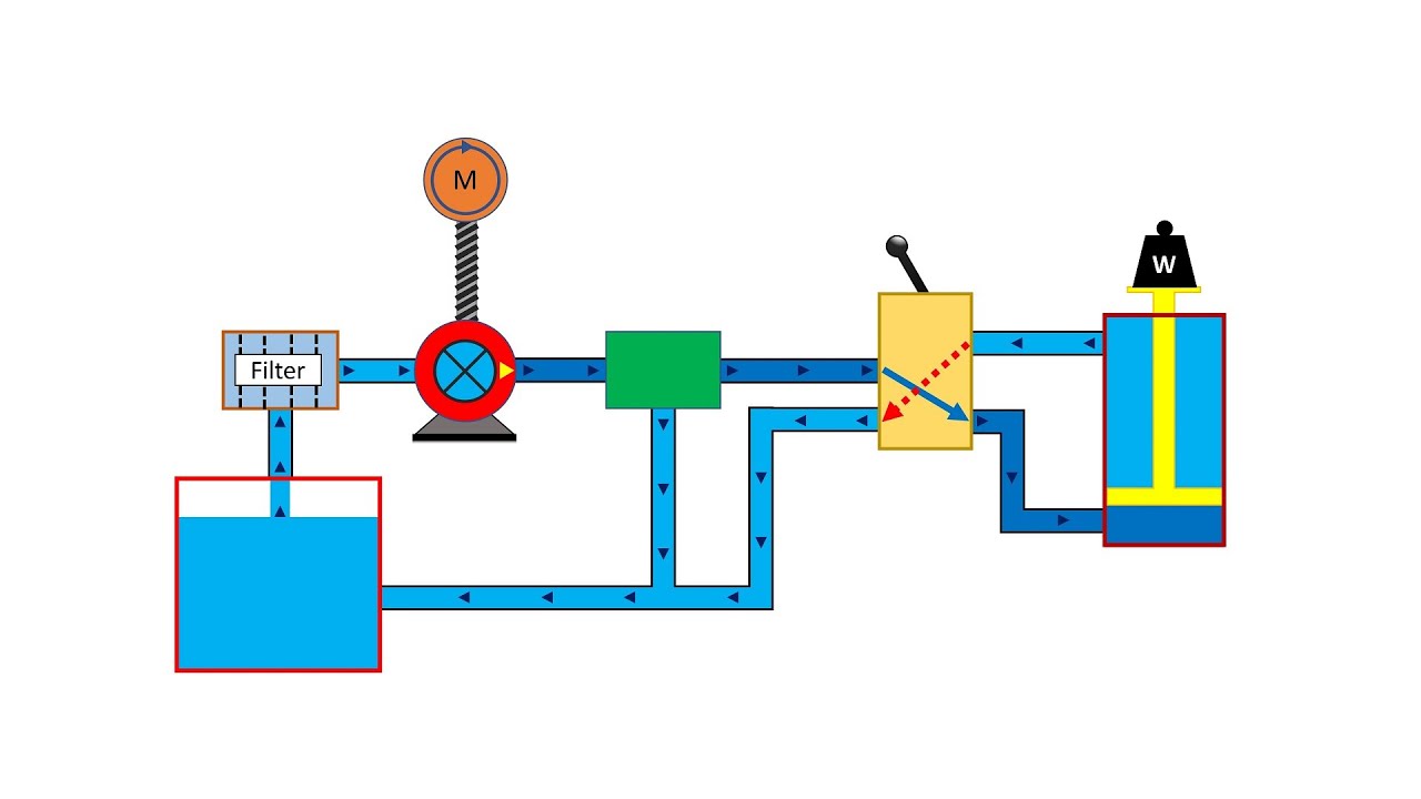
Basic Hydraulic System Circuit Diagram and Working Animation - YouTube
![PEMUDA UMNO BAHAGIAN JASIN: [22+] Hydraulic Wiring Diagram Creator](https://i2.wp.com/hydraulicspneumatics.tpub.com/TM-55-4920-405-13-P/TM-55-4920-405-13-P0059im.jpg)
PEMUDA UMNO BAHAGIAN JASIN: [22+] Hydraulic Wiring Diagram Creator
