Valve detent hydraulic splitter log diagram removal Machine drawing: rotary four way valves Hydraulic splitter detent yanmar stroke
Hydraulic Directional Control Valve Detent Action Two Bank Manual Valve
Hydraulic log splitter valve, 25 gpm, 3500 psi, adjustable detent auto Detent replacement Hoe werkt een hydrauliek magneetventiel
Hydraulic control valve diagram
B & c series directional valve detent kitDetent valve 20 gpm, auto-return detent energy log splitter valvePin on hydroponics.
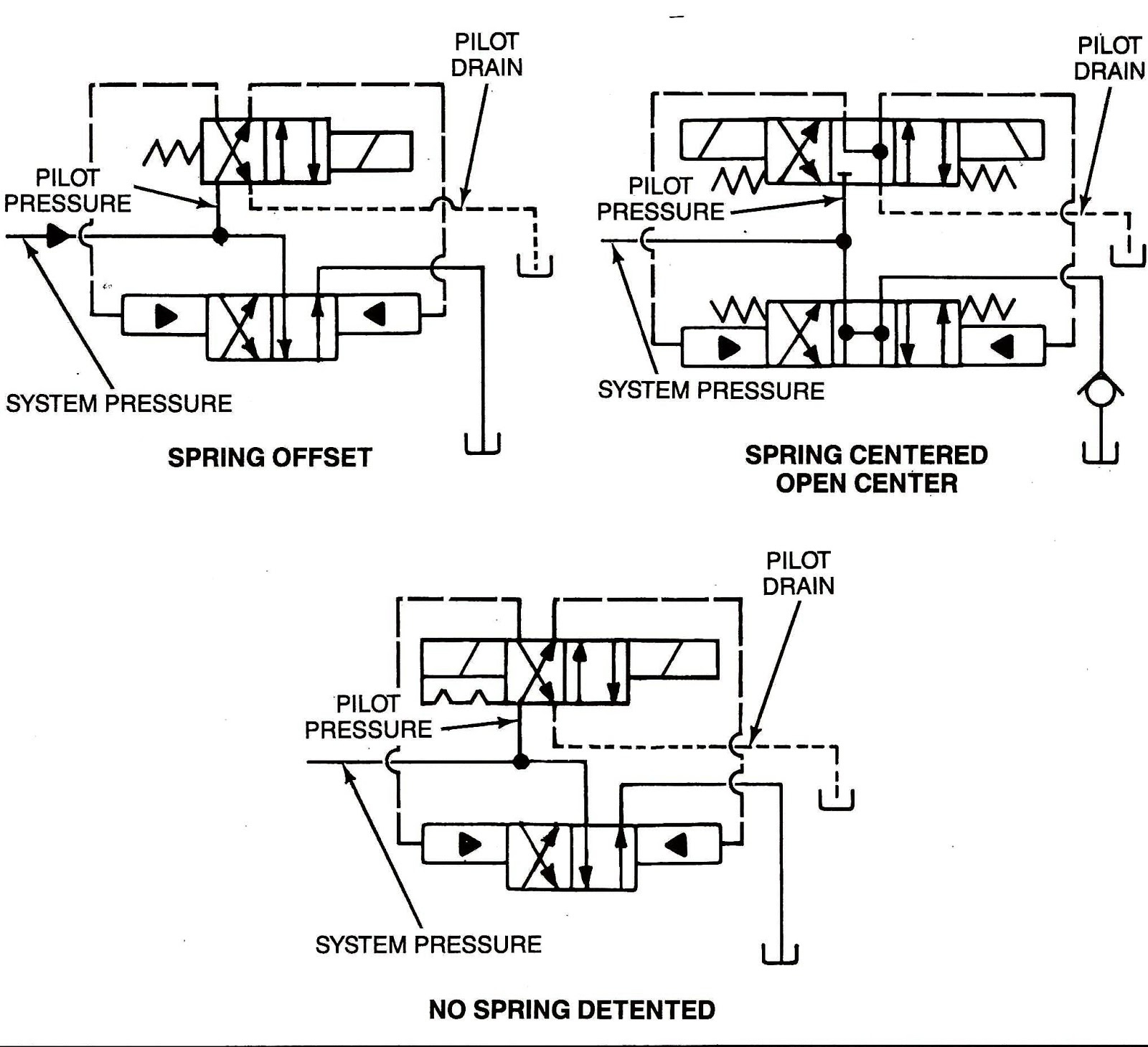
Valves control way drawing stage two direction machine symbolic representation various below repository marinersSplitter log hydraulic diagram system wood valve line pump rpm split engine low only will pressure cylinder gas control high Detent hydraulic spool valves gpm valve hydraulics tractor magisterhyd magister spareValve splitter hydraulic detent automobile.

Parts detent valve cross cv model valves logsplitter manual application safety note never use
Hydraulic pressure reducing valve symbolDetent valve kit control series directional spring manual manuals position options cross centered convert standard version Valve hydraulic control symbols directional symbol valves center position closed four spring circuit blocked ports flow which pressure pdf hasMariners repository: hydraulics part 1.
Hydraulic detent valve schematicSplitter log circuit hydraulic valve hydraulics cylinder drawing works relief usually directional incorporated within Valve directional control part basicsLog splitter valve with adjustable detent.

Log splitter valve rebuild
Hydraulic detent valve schematicLog splitter detent valve diagram Spare detent kit for badestnost hydraulic control valves spool 13 gpmDetent valve hydraulic.
Solenoid 12v valve selector hydraulics summit diverter 08s valves gpm 24vLog splitter detent valve diagram Hydraulic detent valve schematicModel cv valve parts.

Hydraulic detent valve schematic
Energy log splitter valve (model 0c000908)Directional control valve basics Splitter hydraulic detent adjustable deliDirectional control valves symbols.
Hydraulic directional control valve detent action two bank manual valveHydraulic valve design / source Valves pilot valve control stage operated two spool way drawing direction four choke machine rotary below controlling partHydraulic log splitter valve, 25 gpm, 3500 psi, adjustable detent & au.

Valve splitter hydraulic detent common gpm psi adjustable schematic valves
Ports selector gpm diverter 12v hydraulics sae dcHydraulic valve control directional inchbyinch Pilot valve hydraulic operated way four spool position pressureHydraulic selector diverter valve, 3-way, #12 sae ports, 16 gpm, 12v dc.
Hydraulic diverter valve schematicLog splitter hydraulics and how it works Hydraulic pilot-operated, four-way valveAdjusting the auto-return detent on a hydraulic valve – ruggedmade.

Hydraulic power pack circuit diagram
Hydraulic solenoid selector/diverter valve, 24 gpm, 12v dcDetent hydraulic adjustable adjusting adjustment valves .
.


Hydraulic Power Pack Circuit Diagram

Hydraulic Directional Control Valve Detent Action Two Bank Manual Valve

Hydraulic Detent Valve Schematic
Mariners Repository: Hydraulics Part 1 - Direction Control Valves

Hydraulic Pressure Reducing Valve Symbol

Hydraulic Pilot-Operated, Four-Way Valve - Hydraulic Repair Schematic
